
Applications for Lateral Deflection, Angular Rotation and Combined Movements
The selection and proper application of expansion joints for lateral deflection, angular rotation and combined movements, involves the evaluation of a number of variables. These can include the piping configuration, the operating conditions, desired cyclic life, load limitations upon piping and equipment, and available supporting structure. In some cases, two or more types of expansion joints may be suitable for a particular application. The selection then becomes purely an economic one. More frequently one or the other of the available designs possesses unique characteristics which make it particularly suitable, for a given application.
Single Expansion Joints
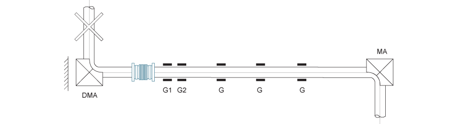
The single expansion joint is usually considered first for any application because it offers the lowest expansion joint cost. The figure below shows a typical application of a single expansion joint absorbing combined axial movement and lateral deflection. The system closely resembles the arrangements shown for axial movement only in the preceding section. The expansion joint is located at one end of the long piping leg with main anchors at each end and guides properly spaced for both movement control and protection of the main anchor (DMA) which, while absorbing the main anchor loading in the direction of the expansion joint axis, permits the thermal expansion of the short piping leg to at upon the expansion joint as lateral deflection. Because the main anchor loading exists only in the piping segment containing the expansion joint, the main anchor loading exists only in the piping segment containing the expansion joint, the anchor at the end of the shorter piping leg is an intermediate anchor.
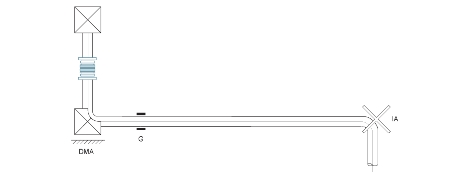
The figure below shows an alternate arrangement in which the expansion joint is installed in the short piping leg and the principal expansion is absorbed as lateral deflection. The longer piping leg is free of compressive pressure loading and requires only an intermediate anchor and directional guiding. The functions of the directional main anchor and the pipe guide may be combined in a single device.
The two figures below represent modifications of the above example, in which the main anchors at either end of the expansion joint are replaced by tie rods. Where the piping configuration permits, the use of tie rods adjusted to prevent axial movement frequently simplifies and reduces the cost of the installation. Because of these tie rods, the expansion joint is not capable of absorbing any axial movement other than its own thermal expansion. The thermal expansion of the piping in the shorter leg, as a result, imposed as deflection on the longer piping leg. Where the longer piping leg is not sufficiently flexible and where the dimension of the shorter leg is suitable, tie rods may be installed spanning the entire short leg, so that no deflection is imposed on the longer run from this source.
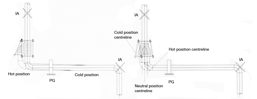
Where appreciable amounts of lateral deflection are imposed upon the expansion joint, some shortening of the expansion joint results from the displacement of the tie rods as shown in the first of the figures below. Care should be taken to ensure that sufficient piping flexibility exists to absorb this deflection and that adequate clearances are provided in the guide to permit deflection of the piping. The amount of this deflection can be minimised by cold springing the expansion joint in the lateral direction as shown in the second figure below. The principal restriction upon the use of single expansion joints for lateral deflection or combined axial movement and lateral deflection is the limited amount of lateral deflection which such an expansion joint can absorb. The allowable lateral deflection is directly proportional to the ratio of convoluted length to diameter which, in turn, is restricted by considerations of stability and manufacturing limitations. While eminently suitable for applications such as the figure above where the principal movement is axial, the relatively small available lateral movement severely limits the type of application illustrated in the figures below. Where operating pressures and temperatures are high, or where availability of suitable structures precludes the use of main anchors and multiple guides, the application shown in the first figure above may not be feasible and another type of expansion joint may result in far more economical installation.
Universal Expansion Joints
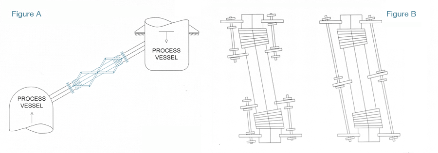
The universal expansion joint is particularly well adapted to the absorption of lateral deflection. In addition, this design may be used to absorb axial movement, angular rotation or any combination of the three. A common application of the universal expansion joint is its use as a tied expansion joint in a 90 degree piping offset with tie rods adjusted to prevent external axial movement. Two such applications are shown in the figures below.
Figure A below shows a tied universal expansion joint used to absorb lateral deflection in a single plane Z bend. Where dimensionally feasible, the expansion joint should be designed to fill the entire offset leg so that its expansion is absorbed within the tie rods as axial movement. The tie rod should be extended to the elbow centre line when practical. The thermal movement of the horizontal lines is absorbed as lateral deflection by the expansion joint.
Both anchors are intermediate anchors since the pressure loading is absorbed by the tie rods. Only directional guiding is required since the compressive load on the pipe consists only of the force necessary to deflect the expansion joint. Any thermal expansion of the offset leg external to the tie rods, such as that of the elbows at either end, must be absorbed by bending of the horizontal pipe legs. Provision should be made in the design of the guides to allow for both this deflection and the reduced length of the expansion joint in its deflection position. In addition, particularly in the case of long universal expansion joints under high pressure, additional allowance may be necessary to compensate for stretching of the tie rods under load. The expansion joint manufacturer should be consulted for recommended minimum guide clearances.
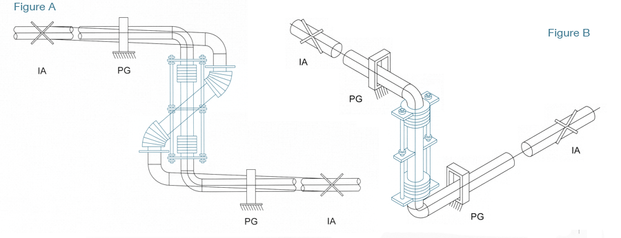
Figure B above shows a typical application of a tied universal expansion joint in a three-plane Z bend. Since the universal expansion joint can absorb lateral deflection in any direction, the two horizontal piping legs may lie at any angle in the horizontal plane.
In cases where a universal expansion joint must absorb axial movement other than its own thermal growth, it cannot function as a tied expansion joint and must be used in combination with main anchors to absorb pressure loading. One such case is shown in Figure A below. The relative expansion between the two vessels results in both axial movement and lateral deflection on the expansion joint. Both vessels must be designed to absorb main anchor loading. Control bars or pantographic linkages may be used to distribute the movement between the bellows and control their movements. Numerous variations are possible in the design of universal expansion joints. Bars, pantographic linkages, slotted hinges or external structural members may be used in a horizontal installation, for example, where it is desirable to support the centre pipe section of the expansion joint independently of the bellows. In a single plane system, the rods may be replaced by two bars with pinned connections at either end of expansion joint. This construction is so commonly used that it has been given the standard nomenclature of swing expansion joint. In some cases two sets of short control bars, each set spanning one of the two bellows in the universal expansion joint are used instead of the overall bars shown in most of the illustrations. This arrangement is frequently used where the control bars are used for control and stability and not for absorption of pressure loading. This can result when the universal expansion joint is very long in relation to its diameter, or a large number of convolutions are used at each bellows of the expansion joint, or where the expansion joint is subject of external forces.
It may be desirable to incorporate control devices in the expansion joint to prevent excessive displacement of the bellows and the relatively free pipe section between them. Figure B above show two forms of controls which may be used for this purpose. In the first figure, short bars are used spanning each of the bellows in expansion joint. Stops are provided on the bars so that, once the expansion joint has reached its rated lateral deflection, the stops will be engaged by members rigidly fastened to pipe portions of the expansion joint. The second figure shows a similar device adapted to an expansion joint with overall bars. The bar stops are engaged by a plate or lug attached to the centre pipe portion and movement of this part beyond its design deflection is restrained. In order to obtain maximum control from these devices, the stops are usually oriented to lie in the plane of resultant movement of the expansion joint, affording maximum leverage as well as greater sensitivity to small movement. Devices of this nature are usually furnished by the manufacturer dependent upon the design characteristics of the expansion joint. Its use is sometimes precluded by the configuration of the piping, the operating conditions or even by manufacturing and transportation limitations. It may be undesirable or impossible to fabricate, ship to the job site and install a universal expansion joint which would span the full length of the offset where, for example, the length of the offset leg in a Z bend is extremely long. When the expansion joint is very long in relation to its diameter, the flexibility of overall bars may reduce the effectiveness of the control so that the centre pipe section becomes unstable. other types of expansion joints may offer a more desirable solution when such limits are encountered.